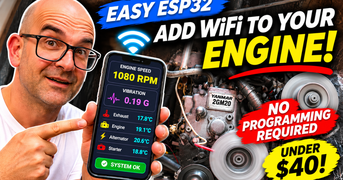
ESP32 Without Coding: Build a WiFi Engine Monitor for Under $40
Can you imagine checking your boat engine’s RPM, temperatures, and vibrations directly from your smartphone, receiving alerts if something goes wrong, and doing it all for under $40? Today, we’re building our own engine monitoring system using an ESP32, a few inexpensive sensors, and ESP Easy. And the best part? No programming experience required!
In this episode of The Low Cost Sailor, we’re transforming our old Yanmar 2GM20 diesel engine into a WiFi-connected engine. This project is particularly useful aboard a sailboat, but it can also be adapted to other engines, machinery, home installations, and countless DIY electronics and Internet of Things (IoT) projects.
ESP32 Made EASY: Add WiFi to Your Engine for Under $40!
In the video, you can follow the entire process, from installing the firmware to testing the system with the engine running. In this article, we’ll take a closer look at the wiring, configuration, and files needed to reproduce the project yourself.
What Are We Going to Build?
Our goal is to install a small device next to the engine that collects information from several sensors and makes it available from any smartphone, tablet, or computer connected to the same WiFi network.
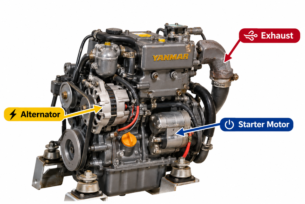
- Four temperature readings: exhaust, engine block, alternator, and starter motor.
- Engine RPM: using a magnet and a Hall effect sensor.
- Vibration monitoring: using an accelerometer to detect changes in engine behavior.
- Temperature alarms: with adjustable thresholds and relay activation.
- WiFi monitoring: directly from a smartphone or computer browser.
- Custom dashboard: a single web page displaying all the readings and controls.
All of this without developing our own firmware from scratch. Most of the work involves configuring ESP Easy through its menus and web forms. For more advanced functions, we’ll use rules that you can simply copy and paste.
1. What Is an ESP32 and Why Should You Use One?
The ESP32 is a family of microcontrollers that has become extremely popular among electronics enthusiasts and professionals. Its main advantages are its low price, WiFi and Bluetooth connectivity — depending on the model — and the enormous range of compatible development boards and sensors.
We can use an ESP32 to control lights, read sensors, automate devices, build instruments, or create monitoring systems. Although these microcontrollers are usually programmed using tools such as Arduino IDE or ESP-IDF, there are alternatives that make them much easier to use.
One of these alternatives is ESP Easy, free firmware that allows us to configure sensors, inputs, outputs, and automation rules through a web interface without writing an entire program.
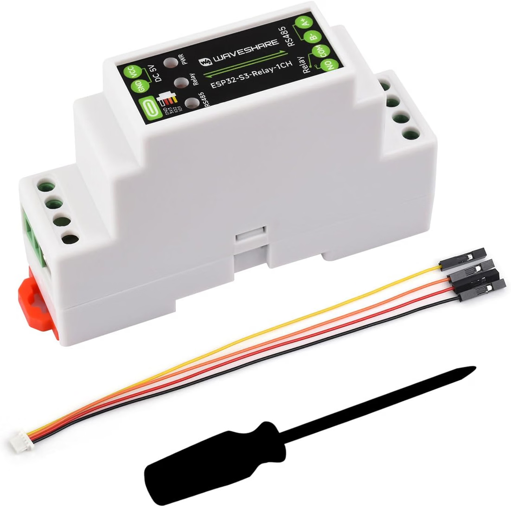
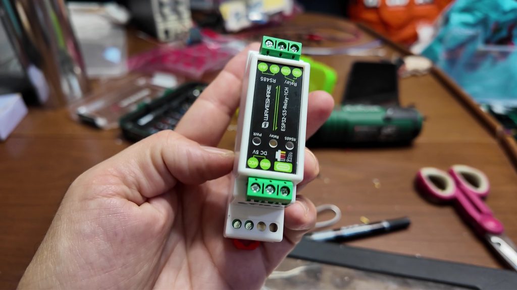
For this project, I’ve chosen a Waveshare ESP32 board with an integrated relay, convenient connectors, and DIN rail mounting. This makes installation much easier and avoids having to build all the electronics from scratch.
2. Required Components and Budget
This project is designed around inexpensive, easy-to-find electronic components. Prices may vary depending on the store, shipping costs, and available offers, but our goal is to keep the entire system below approximately $40.
Waveshare ESP32 Board with Relay
This is the brain of our system. It receives data from the sensors, manages the WiFi connection, and allows us to activate an alarm through its integrated relay.
12V to 5V Power Supply
Since our boat uses a 12V electrical system, we need to reduce the voltage to the level required by the board. One option is to use an enclosed DC-DC step-down converter that provides a regulated output.
- Enclosed voltage regulator on AliExpress
- Enclosed voltage regulator on Amazon.com
- Inexpensive 7805 linear voltage regulator
In my installation, I used a simple 7805 voltage regulator. If you choose this option, you must check the total current consumption, heat dissipation, and power supply conditions. A 7805 dissipates the voltage difference multiplied by the current as heat. For permanent installations, a suitable DC-DC converter with protection against disturbances in the boat’s electrical system is generally preferable.
Four DS18B20 Temperature Sensors
These small digital sensors allow us to measure temperatures using a shared data wire. We’ll use four units, preferably waterproof-style probes with cables, installed at different points around the engine.
MPU6050 Accelerometer
The MPU6050 combines a three-axis accelerometer and a gyroscope. We’ll use it to obtain an indication of engine vibration levels and detect changes compared with the engine’s normal behavior.
A3144 Hall Effect Sensor for RPM Measurement
A Hall effect sensor detects the presence of a magnetic field. By attaching a small magnet to an engine pulley, we can count its rotations and calculate the engine’s revolutions per minute.
- A3144 Hall effect sensor on AliExpress
- A3144 Hall effect sensor on Amazon.com
- Magnets for the DIY tachometer
Other Materials
- Prototyping board
- Connecting wires
- Approximately 4.7 kΩ resistor for the temperature sensor bus.
- Terminal blocks, connectors, mounting brackets, and materials for securing the sensors.
- Suitable wiring and electrical protection for the installation.
Some links in this article are affiliate links. If you purchase through them, you can help support our channel at no additional cost to you.
3. Installing ESP Easy on an ESP32 Without Coding
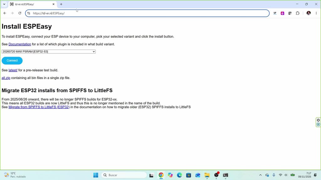
One of the biggest advantages of this project is that we don’t need to write or compile a program. ESP Easy provides tools that allow us to install the firmware directly from a compatible web browser.
Here are the main links:
The general procedure involves connecting the ESP32 to your computer via USB, opening the web installer, selecting a firmware version compatible with your board, and following the installation instructions.
It’s important to choose a firmware build that includes the plugins required for our sensors. The available options may vary between ESP Easy versions.
4. Configuring WiFi and Accessing the ESP32
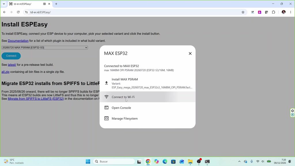
Once the firmware is installed, we configure the device’s WiFi connection so it can communicate with our smartphone or computer.
The ESP32 can connect to an existing network, such as the WiFi router on our boat. We can then access its web interface by entering the IP address assigned to the device.
From this interface, we’ll manage the sensors, outputs, rules, and different operating settings.
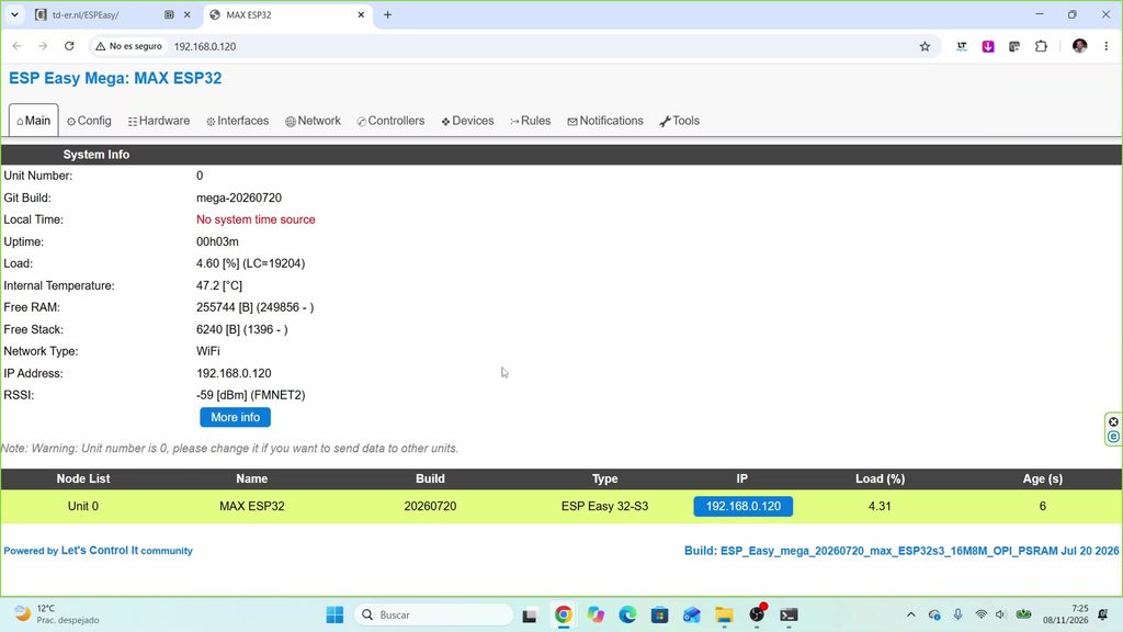
For easier access in a permanent installation, we can reserve an IP address for the ESP32 in our router. It’s also advisable to secure the network and avoid exposing the administration interface directly to the Internet.
5. Configuring the Integrated Relay for Engine Alarms
Our Waveshare board includes an integrated relay that we can use to activate an alarm whenever one of the monitored temperatures exceeds its configured threshold.
On the Waveshare board used in the video, the relay is connected to GPIO47 by design.
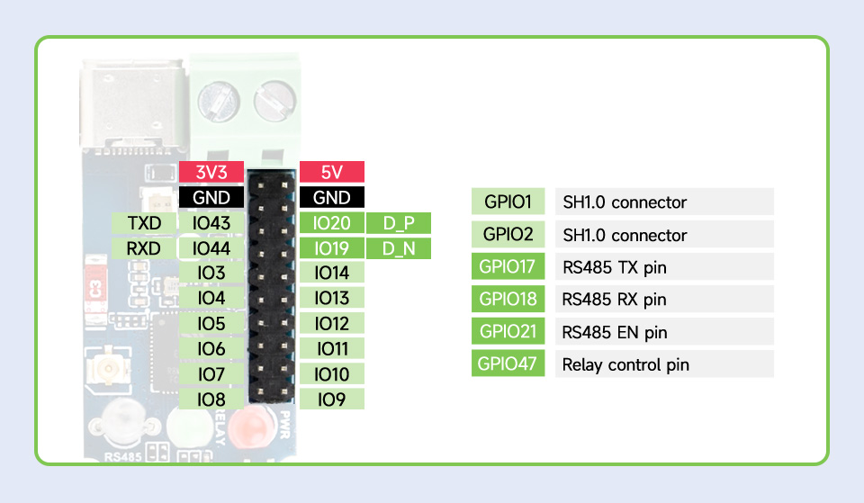
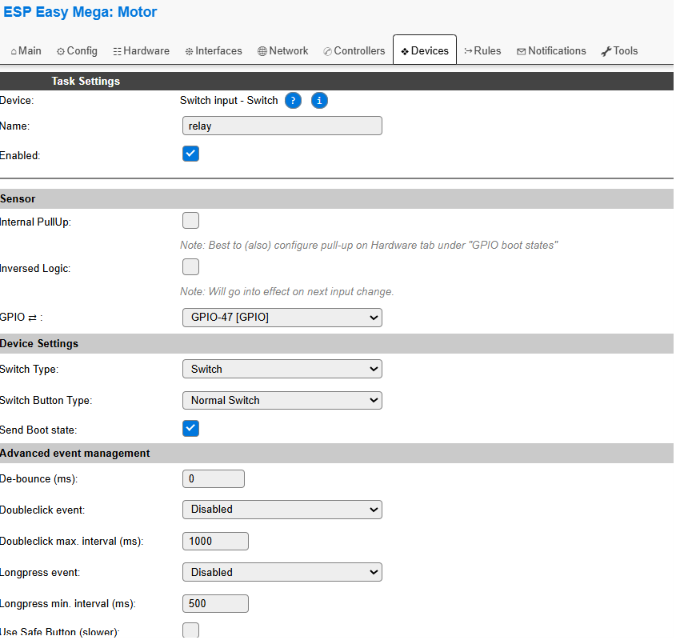
- Open Devices.
- Add a device of type Switch Input – Switch.
- Name it Relay.
- Select GPIO47.
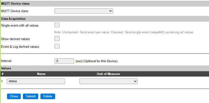
- Save the configuration.
We can test the relay from Tools by sending the following commands:
GPIO,47,1
GPIO,47,0
When executing these commands, we should hear the relay switching. Before connecting a real alarm, verify which state corresponds to each contact position and determine the required safe behavior during startup or a power failure.
6. Measuring Engine Vibrations with an MPU6050
Vibrations can provide valuable information about an engine’s condition. A persistent increase in vibration levels may indicate that something has changed, such as deteriorating engine mounts, imbalance, mechanical problems, or simply changes in engine speed.
To measure vibrations, we’ll use an MPU6050 accelerometer firmly attached to the engine block.
Connecting the MPU6050 via I2C
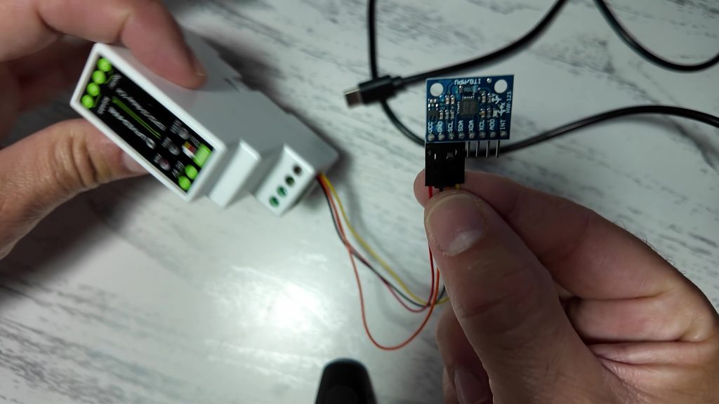
The MPU6050 uses the I2C bus, which allows devices to communicate through two signal lines: SDA and SCL.
| MPU6050 | ESP32 Board Used in the Video |
|---|---|
| GND | GND |
| VCC | Module power supply, depending on the board |
| SDA | GPIO1 |
| SCL | GPIO2 |
On my Waveshare board, I use the I2C connector with black, red, yellow, and orange wires. The red wire provides 5V, so we must verify that our MPU6050 module supports this voltage on its VCC input. Some modules include a voltage regulator, but not all of them do. The ESP32’s I2C signals must use voltage levels compatible with 3.3V.
Configuring the MPU6050 in ESP Easy
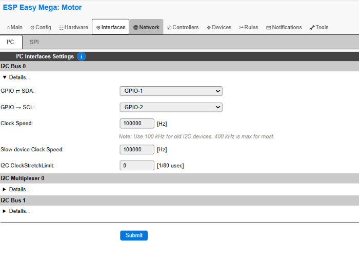
- Open Interfaces and enable I2C.
- Configure SDA = GPIO1 and SCL = GPIO2.
- Select a bus speed of 100 kHz.
- Save the settings and run Tools > I2C Scan.
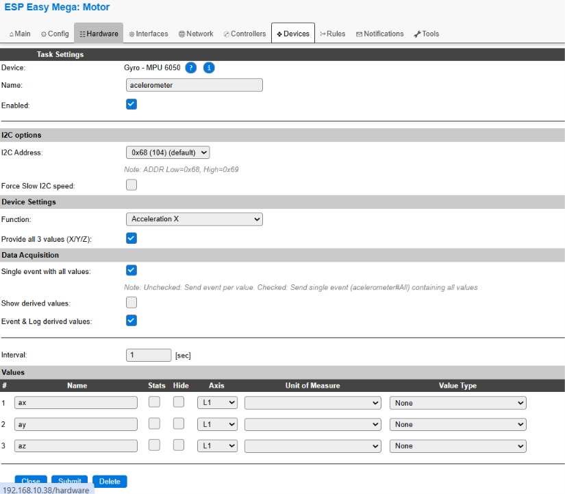
- The MPU6050 will normally appear at address 0x68.
- Under Devices, add the MPU6050 plugin, select the detected address, and configure acceleration readings for all three axes with a one-second interval.
How Can We Convert Acceleration Readings into a Vibration Indicator?
The accelerometer provides readings along three axes: X, Y, and Z. However, if we want to know whether our engine is vibrating more than usual, it’s much more convenient to have a single indicator that we can monitor over time.
We can calculate a magnitude from the three acceleration values, remove or compensate for the static component caused by gravity, and smooth out rapid variations. The exact method depends on how we want to represent vibration and the capabilities of our ESP Easy version.
It’s important to understand that we’re not building a calibrated industrial vibration meter. Our goal is to obtain a comparative indicator: establish how much the engine normally vibrates at different RPM levels and detect abnormal increases.
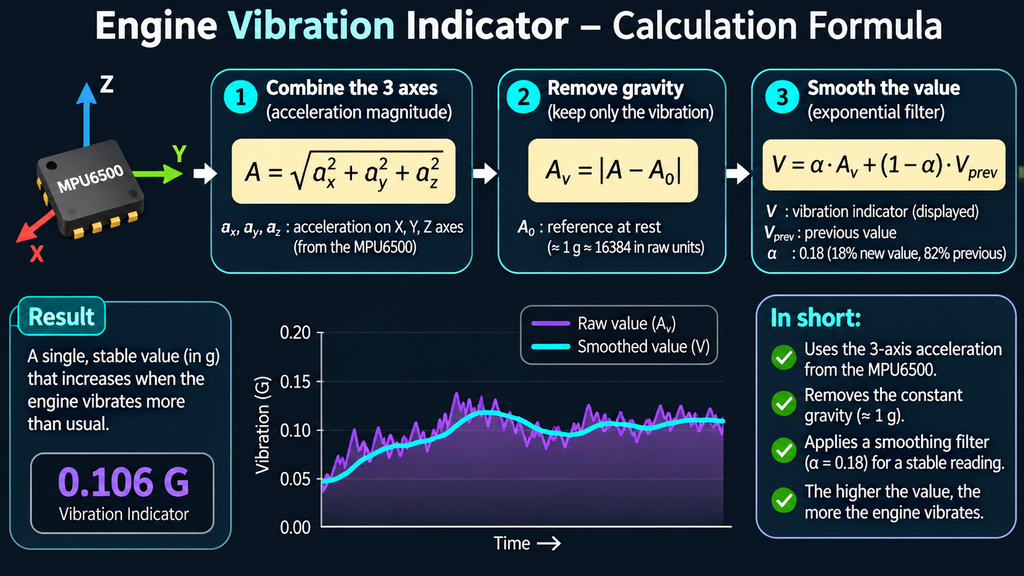
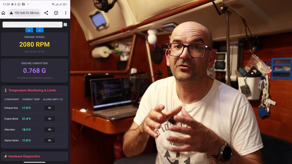
For meaningful comparisons, measurements should always be taken at similar engine speeds and with the sensor mounted in the same position.
7. Monitoring Four Temperatures with DS18B20 Sensors
One of the most useful features of our system is the ability to monitor temperatures at different points around the engine.
DS18B20 sensors use the digital 1-Wire protocol, allowing several temperature probes to share the same ESP32 GPIO pin. Each sensor has a unique identifier, so ESP Easy can recognize them individually.
Wiring the Four Temperature Probes
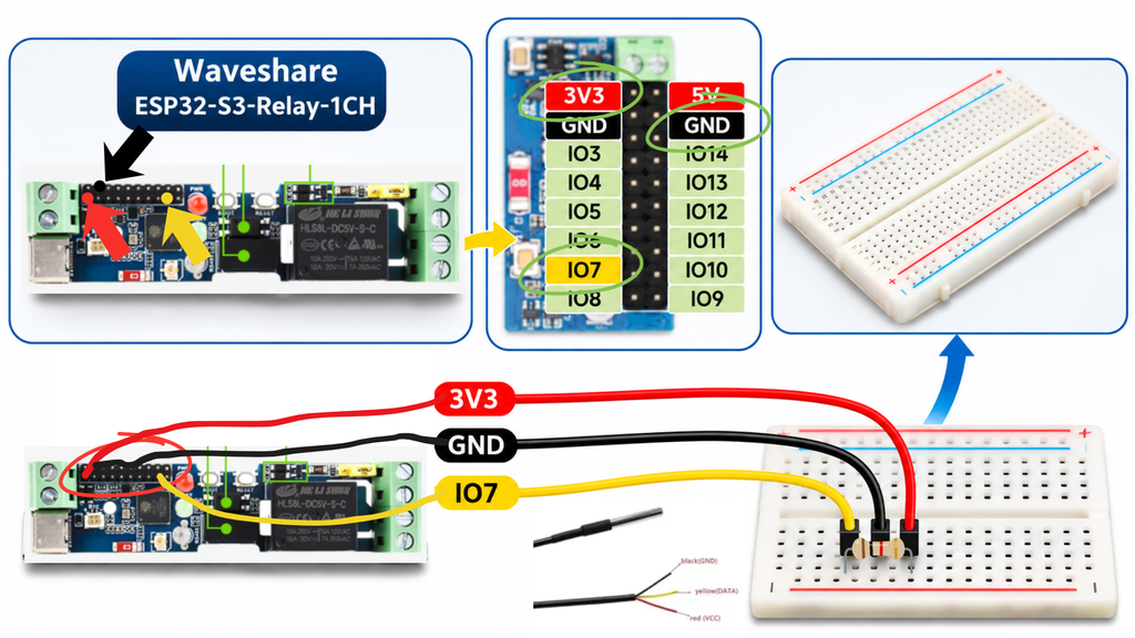
In our installation, we use GPIO7 to communicate with all four sensors.
- Connect all sensor power wires to 3.3V.
- Connect all ground wires to GND.
- Connect all data wires to GPIO7.
- Install an approximately 4.7 kΩ resistor between 3.3V and GPIO7.
On the probes I used, the yellow wire is the data line. However, always check the manufacturer’s wire color coding before making the connections.
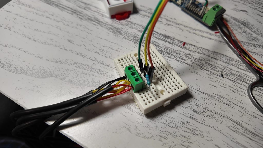
Configuring DS18B20 Sensors in ESP Easy
Under Devices, add a device of type Environment – DS18xxx, select GPIO7, and set a five-second reading interval.
Next, select the address corresponding to one of the sensors. Repeat the process until you have four independent temperature devices configured.
| Sensor | Location | Purpose |
|---|---|---|
| 1 | Exhaust | Monitor temperature changes |
| 2 | Engine block | Monitor engine heating |
| 3 | Alternator | Detect abnormal temperatures |
| 4 | Starter motor | Monitor its temperature |
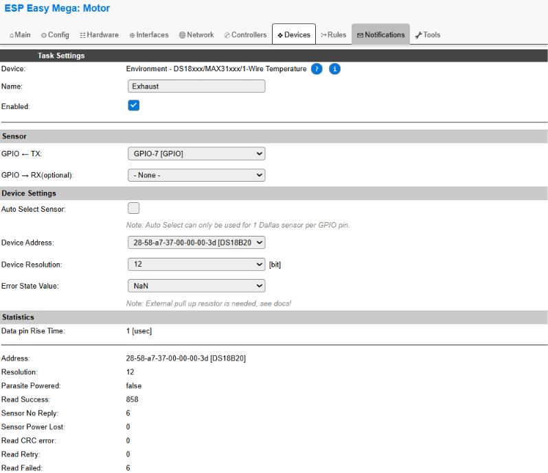
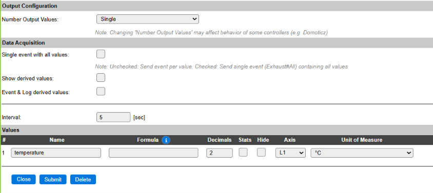

To identify which address belongs to each sensor, we can gently warm one probe with our hand and observe which temperature reading changes.
Important: standard DS18B20 sensors have a limited measurement range, generally up to 125°C at the sensor itself. A probe attached to the outside of an exhaust pipe measures the temperature at that contact point, not necessarily the temperature of the gases flowing inside. Always ensure that the actual temperature remains within the specifications of the sensor, cable, and enclosure.
8. Building a DIY Engine Tachometer with an A3144 Hall Effect Sensor
To measure engine RPM, we need to detect how many revolutions the engine completes over a given period.
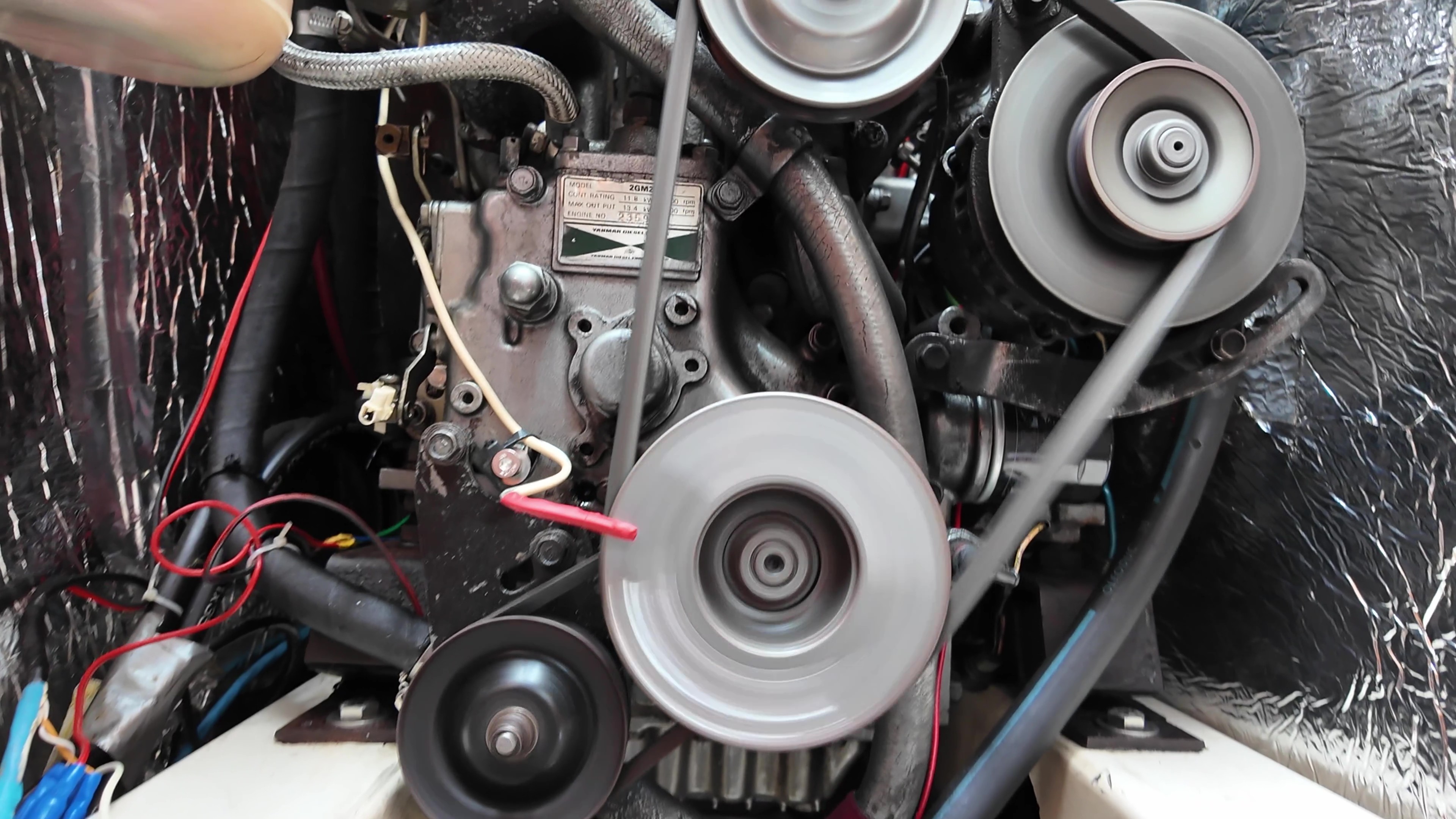
Instead of using the original Yanmar tachometer signal, which was giving me quite a few headaches, I decided to use a much simpler solution: a magnet attached to an engine pulley and a Hall effect sensor.
Every time the magnet passes in front of the sensor, it generates a pulse. By counting these pulses, we can calculate the engine’s RPM.
Connecting the A3144 Hall Sensor
| Hall Sensor | ESP32 |
|---|---|
| VCC | 3.3V, if the module is compatible |
| GND | GND |
| OUT | GPIO11 |
The wiring above corresponds to the module used in the video. If you’re using a standalone A3144 sensor, check its operating voltage, pinout, and pull-up resistor requirements. Not all commercially available modules are identical.
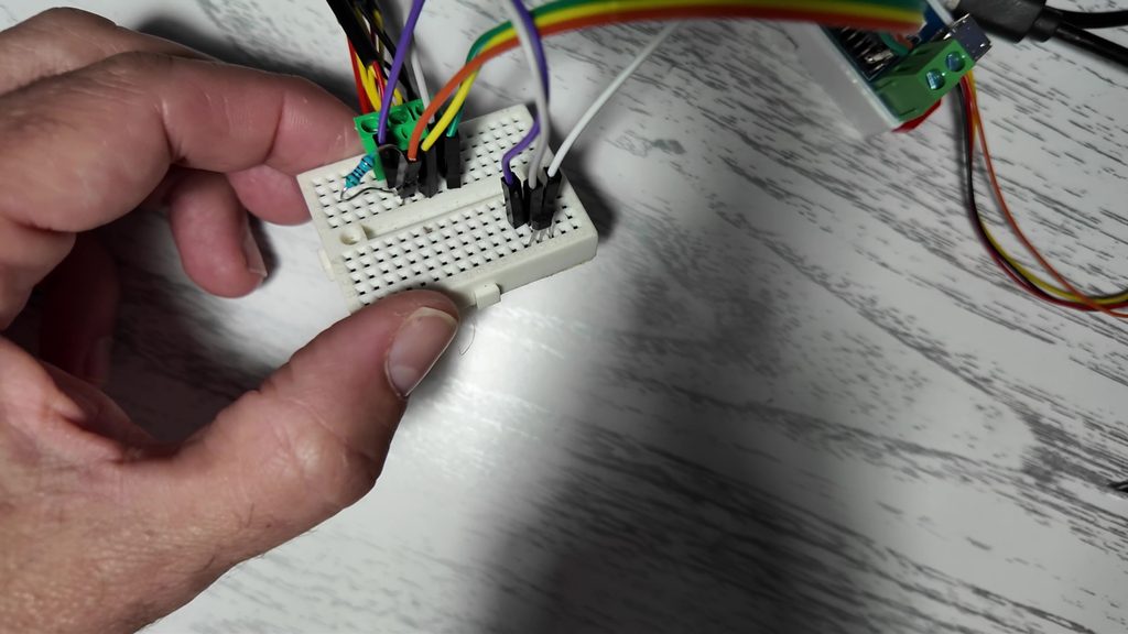
Configuring the Pulse Counter
Under Devices, add a Generic – Pulse Counter device and use the following settings:
| Parameter | Setting |
|---|---|
| GPIO | GPIO11 |
| Internal pull-up | Enabled |
| Debounce | 2 ms |
| Counter type | Delta |
| Mode | Falling |
| Interval | 1 second |
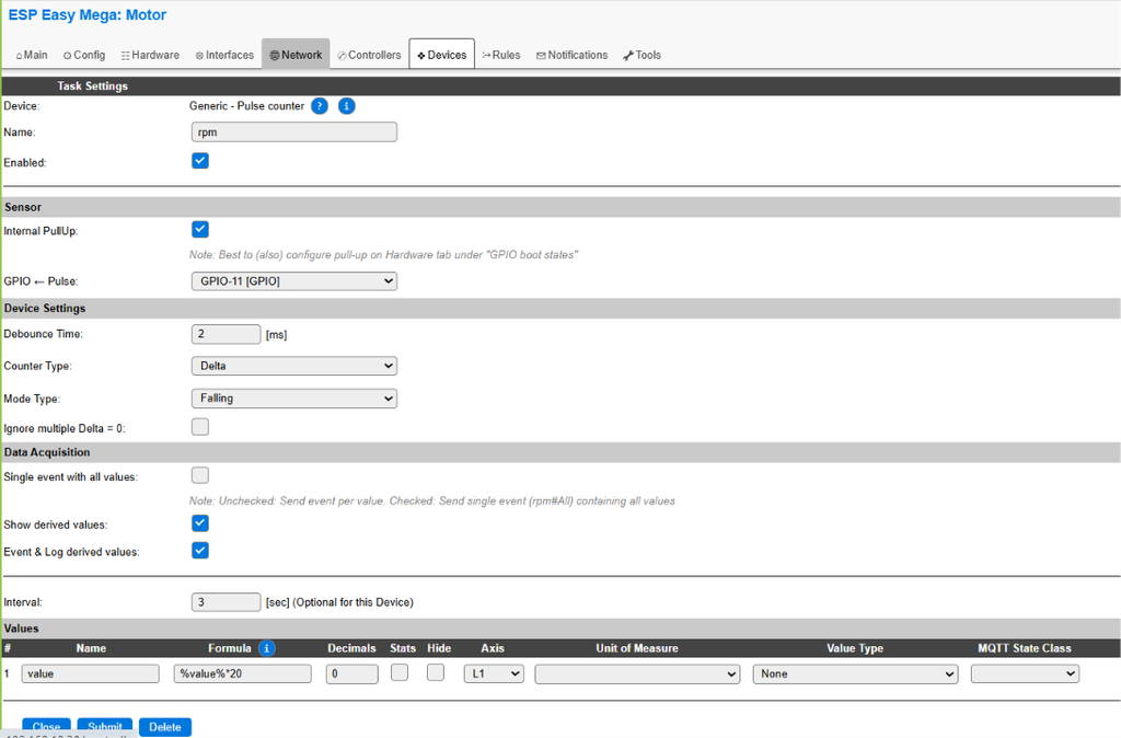
Formula for Calculating Engine RPM
If we use a single magnet and the pulley completes exactly one revolution for every revolution of the crankshaft, each pulse represents one engine revolution.
Since there are 60 seconds in a minute, the calculation is very simple:
RPM = Pulses per second × 60In the ESP Easy value formula field, we can use:
%value%*60This formula assumes that the counter provides the number of pulses recorded during a one-second interval. If we change the measurement interval, the number of magnets, or the ratio between the pulley and crankshaft, we’ll need to adjust the calculation accordingly.
For example, if the pulley rotates twice for every crankshaft revolution, we cannot use the same formula without correcting for the pulley ratio.
We should also remember that counting pulses over just one second can produce fluctuations in the RPM reading. We can smooth the readings by increasing the measurement interval or applying an average, although this will make the display respond slightly more slowly.
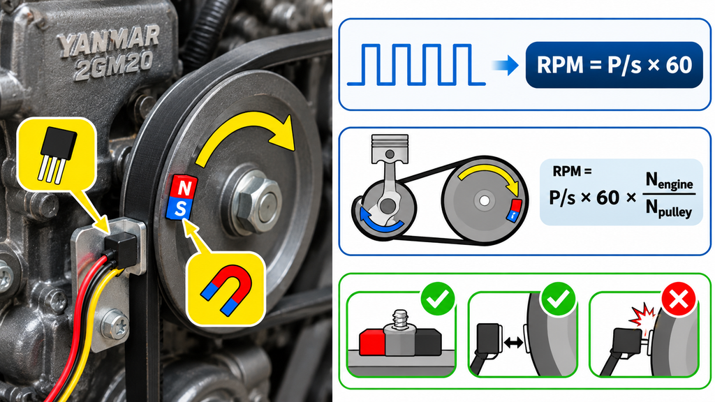
Important: the magnet must be securely attached, and the sensor must be mounted on a rigid bracket with no possibility of touching the pulley, belt, or any other moving component.
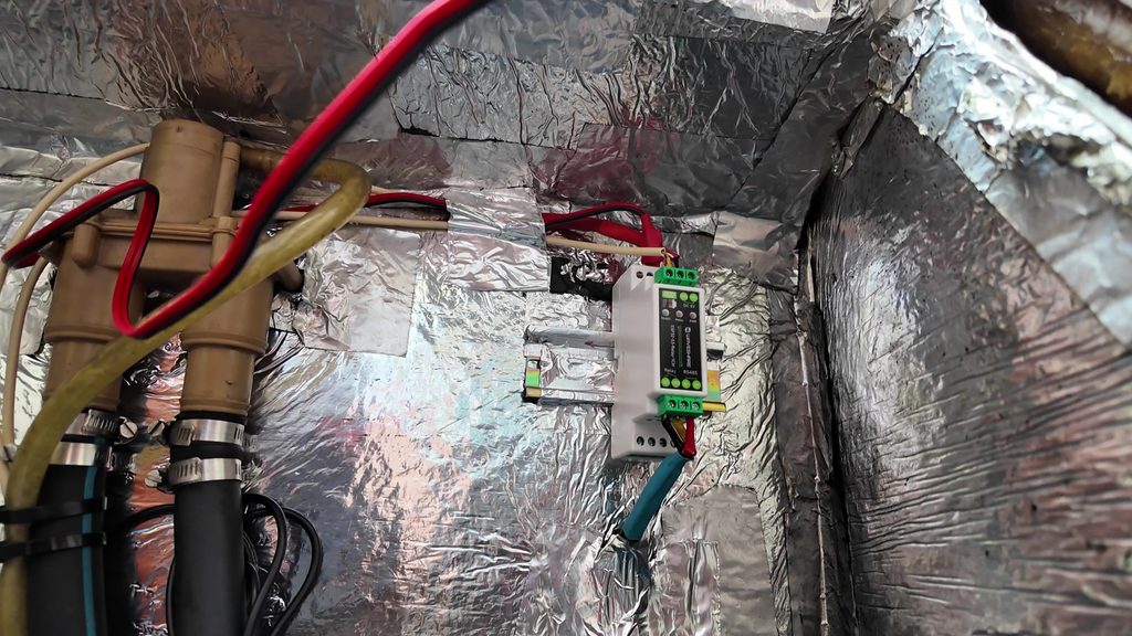
9. Final Assembly and Installation on the Engine
Once we’ve confirmed that all the sensors are working correctly, it’s time to install the system inside the engine compartment.
This is a much more demanding environment than our workbench. We have vibrations, moisture, high temperatures, electrical wiring, and moving mechanical components.
That’s why we need to pay particular attention to securing the sensors, protecting the wiring, providing proper electrical insulation, and choosing a suitable location for the electronics.
Cables should be secured to prevent rubbing, kept away from belts and pulleys, and connected using suitable connectors. The power supply must have appropriate electrical protection and be compatible with the real operating conditions of the boat’s electrical system.
10. Creating Automatic Temperature Alarms with ESP Easy
So far, we’ve managed to read all our sensors, but now we want to go one step further: make the ESP32 monitor the temperatures automatically and activate an alarm whenever an excessive value is detected.
To achieve this, we’ll use ESP Easy rules, which allow us to execute actions whenever specific conditions are met.
Creating Adjustable Temperature Limits
Since we still need to establish the engine’s normal operating temperatures under different conditions, I want to be able to change the alarm thresholds easily without rewriting the rules.
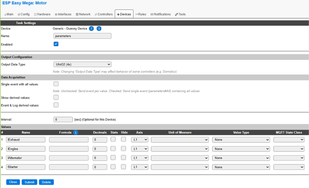
To do this, we add a Dummy Device with four variables:
lExhaust
lEngine
lAlternator
lStart
These variables store the temperature limits for the exhaust, engine block, alternator, and starter motor.
During my initial tests, I used 90°C as a temporary threshold, but this should not be interpreted as a universal maximum temperature or a recommended setting for every engine component.
The final thresholds must be established according to the engine specifications, the exact location of each sensor, and the normal temperatures observed during operation.
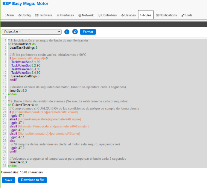
ESP Easy Rules: Ready to Copy and Paste
These rules initialize the temperature limits, preserve the configured values using the selected persistence mechanism, and activate the relay whenever one of the temperatures exceeds its threshold.
We must also consider what happens when temperatures return to normal, how the alarm behaves after a restart, and what should happen if a sensor stops responding.
// 1. Initialization and start of the monitoring loop
on System#Boot do
  LoadTaskSettings,8

  // If parameters are empty, initialize them to 90°C
  if [parameters#lExhaust]=0
    TaskValueSet,8,1,90
    TaskValueSet,8,2,90
    TaskValueSet,8,3,90
    TaskValueSet,8,4,90
    SaveTaskSettings,8
  endif

  // Start the engine safety loop (Timer 8 runs every 3 seconds)
  timerSet,8,3
endon

// 2. Continuous alarm monitoring loop (runs every 3 seconds)
on Rules#Timer=8 do
  // Check whether ANY danger condition is directly met
  if [Exhaust#temperature]>[parameters#lExhaust]
    gpio,47,1
  elseif [Engine#temperature]>[parameters#lEngine]
    gpio,47,1
  elseif [Alternator#temperature]>[parameters#lAlternator]
    gpio,47,1
  elseif [Starter#temperature]>[parameters#lStarter]
    gpio,47,1
  else
    // If none of the conditions is true, turn off the relay
    gpio,47,0
  endif

  // Schedule the timer again to repeat the loop every 3 seconds
  timerSet,8,3
endon

// 3. Independent timers for saving data to flash memory
on parameters#lExhaust do
  timerSet,1,2
endon

on parameters#lEngine do
  timerSet,1,2
endon

on parameters#lAlternator do
  timerSet,1,2
endon

on parameters#lStarter do
  timerSet,1,2
endon

// When Timer 1 reaches zero, permanently save Task 8
on Rules#Timer=1 do
  SaveTaskSettings,8
endon
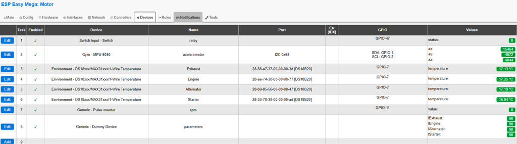
Before using these rules, check that the device names and variables match your own configuration exactly. If you change any of these names, you’ll also need to update their references in the rules and dashboard.
The electronic alarm is an additional monitoring system. It must not replace the engine’s original protection systems, especially oil pressure and overheating alarms.
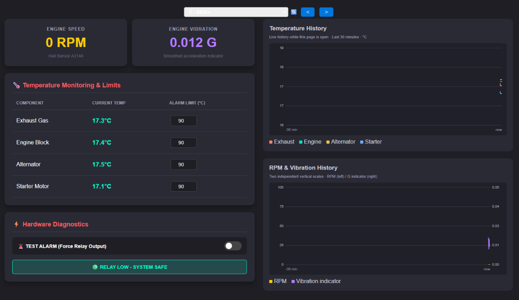
11. Creating a Custom Dashboard to Monitor the Engine from Your Phone
Once all the sensors are configured, we can already check their readings through the ESP Easy interface. However, navigating through different configuration screens isn’t particularly convenient for everyday use.
That’s why I’ve created, with the help of artificial intelligence, a custom engine monitoring dashboard that brings all the information together on a single page.
- Engine RPM readings.
- Vibration indicator.
- Temperatures from all four sensors.
- Adjustable alarm thresholds.
- Relay status and diagnostic controls.
The dashboard is designed to work on both computers and smartphones.
Downloading and Installing the Dashboard
The dashboard page is named dashboard.sp, and we can install it directly through the ESP Easy web interface.
Dashboard download:
Download the dashboard file here
Once downloaded:
- Access the ESP32 web interface.
- Open Tools > File Browser.
- Upload the dashboard.sp file to the root of the file system.
- Restart the device from Tools.
- Open your browser and enter the ESP32’s IP address followed by /dashboard.sp.
For example, if our ESP32 has the IP address 192.168.1.100, the dashboard URL will be:
http://192.168.1.100/dashboard.spOf course, you’ll need to replace this example address with your device’s actual IP address.
The dashboard must use the same device and variable names configured in ESP Easy. If your installation differs from mine, you may need to adjust some references.
12. ESP32 GPIO Wiring Summary
To make it easier to reproduce the project, here’s a summary of the GPIO connections used in the video with our Waveshare board:
| Function | Connection | Device |
|---|---|---|
| Alarm relay | GPIO47 | Integrated relay |
| I2C SDA | GPIO1 | MPU6050 |
| I2C SCL | GPIO2 | MPU6050 |
| Temperature sensors | GPIO7 | 4 × DS18B20 |
| Engine RPM | GPIO11 | A3144 Hall effect sensor |
These GPIO assignments correspond to the specific board used in this project. If you’re using a different ESP32 board, check its wiring diagram, available pins, and any reserved functions before reproducing the connections.
13. What Other Projects Can We Build with an ESP32?
This engine monitor is just one example of what we can achieve with an ESP32. Once we learn how to connect sensors, configure WiFi, and use ESP Easy, a whole world of possibilities opens up for our boats.
We could build battery monitoring systems, tank level sensors, environmental monitors, alarms, remote controls, or even navigation instruments. And if we eventually decide to write our own firmware, the possibilities become even greater.
At The Low Cost Sailor, we’ll continue exploring this technology in future projects while always following our philosophy: useful, affordable solutions that we can build ourselves.
14. Frequently Asked Questions About ESP32 and ESP Easy
Do I Need Programming Experience to Use an ESP32?
Not necessarily. Although the ESP32 is a programmable microcontroller, ESP Easy allows us to configure many sensors, inputs, outputs, and automations through a web interface. Some advanced features, such as custom rules, require entering instructions, but we can reuse configurations that have already been prepared.
Can I Use a Different ESP32 Board?
Yes, provided it’s compatible with an ESP Easy version that includes the required plugins. You’ll need to adapt the GPIO assignments, power supply, and relay connections to your specific board.
Do I Need an Internet Connection to Monitor My Engine?
No. Once installed and configured, the system can operate entirely over a local WiFi network without Internet access. Your smartphone and ESP32 simply need to be able to communicate through that network.
Can I Connect More Temperature Sensors?
The 1-Wire protocol allows multiple DS18B20 sensors to share the same data bus. The practical number of sensors depends on wiring length, power supply, signal quality, and the resources available in the firmware.
Will This System Work with Other Engines?
Yes. Although we’ve installed it on a Yanmar 2GM20, the same concept can be adapted to other diesel engines, gasoline engines, and machinery. You’ll need to adjust sensor locations, pulley ratios, and temperature thresholds accordingly.
Is This System Reliable Enough to Protect My Engine?
It’s an additional monitoring tool that can help detect abnormalities. However, it does not replace the engine’s original protection systems or guarantee that every failure will be detected. The sensors and alarms should be tested regularly.
Conclusion: A WiFi-Connected Engine for Under $40
Using an ESP32 board, four temperature probes, an accelerometer, and a Hall effect sensor, we’ve built a system capable of monitoring our engine over WiFi and activating alarms when excessive temperatures are detected.
But the most interesting part of this project isn’t just the money we’ve saved. It’s discovering how easy it can be to use a microcontroller like the ESP32 to build genuinely useful devices, even if we’ve never programmed one before.
If you enjoyed this DIY project, don’t miss the full video, subscribe to our channel, and let us know in the comments what other projects you’d like us to build.
🎬 Watch the video: ESP32 Made EASY: Add WiFi to Your Engine for Under $40!
❤️ Support The Low Cost Sailor
If you found this project useful, you can help us continue creating videos, tutorials, and affordable DIY inventions for our boats.
- ❤️ Support us through PayPal
- ❤️ Become a supporter on Patreon
- 🛒 Support us by shopping through our Amazon.com link
- 🛒 Support us by shopping through our AliExpress link
Fair winds, and see you in our next DIY project! ⛵